
General explanation
The blog explains the different ignition models that were originally delivered on Puch models. It also explains which ignition model fits which engine type. In addition, it explains how to adjust the ignition points.
The automatic models ( for example, the E50 engine ) came with a right-turning flywheel. These models also work exclusively with the right-hand rotating flywheel. The models with gears ( e.g. the MV/ VS/ DS etc. ) were only supplied with a left-turning flywheel. These models also work exclusively with the left-turning flywheel. So before ordering and/or fitting a flywheel, check carefully whether it is a left- or right-hand drive version.
Puch mopeds came with 3 different ignition types:
- Bosch
- Iskra
- Ducati
These ignition types are practically the same, the only difference is that they come from a different factory. When fitting, it is important that the flywheel and base plate are 1 set ( i.e. of the same type ). Different contact points and capacitors were also used over the years. These contact points were with or without wire and the capacitors with nut or as a soldered version.
The mounting holes of the 3 different types are the same. As a result, the different replacement parts available in the webshop fit the 3 models.
Basic explanation contact points ignition
An original model contact points ignition is shown below. Each part is named separately:
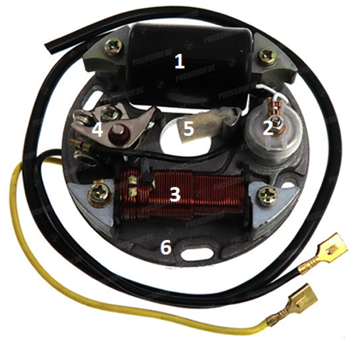
- The ignition coil. The coil generates current to create a spark. This current is passed on to the capacitor and the contact points. From the ignition coil, the ignition cable goes to the spark plug cap and spark plug.
- The capacitor. The function of the capacitor is simple, it takes in current and releases it. This gives you a voltage high enough to create a spark.
- Light coil. The name already says it all, this coil provides the moped with light. The yellow wire is the power supply for the lights, which in the case of a Puch Maxi S is 6 volts
- Breaker points. The contact points open and close at high speed, creating a pulse an ignition. So the function of the contact points is to briefly connect and shortly open again. The small cam on the contact points runs over the cam on the flywheel.
- Felt. The small piece of felt also runs across the cam of the flywheel, its function being to keep the cam clean.
- Base plate/base plate. This plate is the basis for the ignition, on which all components are mounted. The plate is important when adjusting the ignition, more about this later.
Adjusting the original contact points ignition ( left and right turning)
Adjusting supplies:
- Caliper or micrometer with inclusion for the correct spark plug hole
- Sparke plug wrench
- Feeler gauge
- Screwdriver (flat and cross)
Correct ignition point adjustment is very important for moped performance and component preservation. By adjusting the ignition, we want to achieve that the ignition fires at the right are spark. We can adjust the ignition points with the following operations:
- Turning the ignition base plate to the left or right
- Increasing or decreasing the distance between contact points
- Start by removing the flywheel cover. Now that the flywheel cover is gone, you can look inside the flywheel.
- First of all, we want to know whether the contact points open far enough. We want to measure the size between the 2 contact points, which should be 0.35 millimetres. The only way to measure this is with a feeler gauge.
- On the inside of the flywheel, there is a bushing in the centre over which the cam of the contact point runs. This bushing has a thickening at one point, this makes the contact point open close. Put the cam of the contact point on the thickening of the bushing in the flywheel.
- Loosen the bolt that holds the contact point. Now measure the 0.35 millimetre with the feeler gauge between the contact points. Then tighten the bolt again and make sure the lug of the contact point is against the bushing in the flywheel.
- Once the contact point is adjusted, check that the size is correct. Turn the flywheel a full turn and check again the size between the contact point.
- Now we can start checking whether the ignition is on "time". Remove the spark plug and turn the micrometer into the spark plug hole or insert the pin of the caliper into the spark plug hole.
- The goal is to start looking for the top dead centre. By this we mean the highest point of the piston in the cylinder. Turn the flywheel in the specified direction (left or right) until the value on the micrometer or caliper remains the same.
- We consider this point to be 0 point, from this point we measure the pre-ignition. This is the measure before the piston reaches top dead centre.
- We now set the caliper or micrometer to the desired pre-ignition. We use the following values
- Standard 49cc cylinder 1.1 millimetres
- 50cc fast/70cc or above 1.4 millimetres. - We add this value to the zero point set earlier. This means that ignition takes place at 1.1 millimetres or 1.4 millimetres before the top dead centre.
- Now that the caliper or micrometer is properly set, you can start adjusting the required pre-ignition. Turn the micrometer in the spark plug hole again, or insert the caliper in the spark plug hole. Turn the piston in the indicated direction (right or left) until the piston touches the caliper or micrometer.
- The contact points should start to open at this size. Should this not be the case, the base plate must be rotated. By turning the base plate, we can set the ignition "earlier" or "later". This means that the contact points can open earlier or later.
- If the contact points are already fully open, it means that the ignition should be a bit earlier so that the contact points open later. If the contact points remain closed the ignition should be later so they open earlier. If the baseplate is rotated counterclockwise the ignition will be earlier. If it is turned clockwise, it gets later.
Checking the adjustment with a strobe lamp
Adjusting supplies:
- Caliper or micrometer with inclusion for the correct spark plug hole
- Sparke plug wrench
- Feeler gauge
- Screwdriver (flat and cross)
- Timing induction lamp
- Battery 12 volts
Using a timing induction lamp, we can check the ignition adjustment. This is a very precise way of tuning. The first part of the adjustment is similar to the adjustment with the micrometer or caliper:
- Start by removing the flywheel cover. Now that the flywheel cover is gone, you can look inside the flywheel.
- First of all, we want to know whether the contact points open far enough. We want to measure the size between the 2 contact points, which should be 0.35 millimetres. The only way to measure this is with a feeler gauge.
- On the inside of the flywheel, there is a bushing in the centre over which the cam of the contact point runs. This bushing has a thickening at one point, this makes the contact point open close. Put the cam of the contact point on the thickening of the bushing in the flywheel.
- Loosen the bolt that holds the contact point. Now measure the 0.35 millimetre with the feeler gauge between the contact points. Then tighten the bolt again and make sure the lug of the contact point is against the bushing in the flywheel.
- Once the contact point is adjusted, check that the size is correct. Turn the flywheel a full turn and check again the size between the contact point.
- Now we can start checking whether the ignition is on "time". Remove the spark plug and turn the micrometer into the spark plug hole or insert the pin of the caliper into the spark plug hole.
- The goal is to start looking for the top dead centre. By this we mean the highest point of the piston in the cylinder. Turn the flywheel in the specified direction (left or right) until the value on the micrometer or caliper remains the same.
- We consider this point to be 0 point, from this point we measure the pre-ignition. This is the measure before the piston reaches top dead centre.
- We mark this point on the flywheel and on the engine block. On top of the flywheel we put a line, a line should also be put on the crankcase. These 2 stripes should be on 1 line, which is the top dead center.
- We now set the caliper or micrometer to the desired pre-ignition. We use the following values:
- Standard 49cc cylinder 1.1 millimetres
- 50cc fast/70cc or above 1.4 millimetres. - We add this value to the zero point set earlier. This means that ignition takes place at 1.1 millimetres or 1.4 millimetres before the top dead centre.
- Now that the caliper or micrometer is properly set, you can start adjusting the required pre-ignition. Turn the micrometer in the spark plug hole again, or insert the caliper in the spark plug hole. Turn the piston in the indicated direction (right or left) until the piston touches the caliper or micrometer.
- This point is the point where the contact points should begin to open. On the flywheel and on the crankcase there should be another line. When these 2 lines come across one, the correct pre-ignition is set.
- The contact points should therefore start to open at this size. If this is not the case, the base plate must be rotated. By turning the base plate, we can set the ignition "earlier" or "later". This means that the contact points can open earlier or later.
- If the contact points are already fully open, it means that the ignition should be a little earlier so that the contact points open later. If the contact points remain closed the ignition should be later so they open earlier. If the baseplate is turned counterclockwise the ignition is earlier. If it is turned clockwise, it gets later.
- Now we can connect the strobe light, we do this on a 12 volt battery. The red clamp that comes with the strobe light must be connected to the spark plug wire. Note : there is a direction on this clamp. Start the moped and aim the lamp at the 2 sets of stripes on the flywheel and crankcase. Press the button of the lamp, the lamp will start flashing. The flashing will make the stripes clearly visible, the stripes should match while flashing. If they do , the ignition is set correctly. Should this not be the case, the base plate must be rotated further to achieve the correct ignition timing
- The above adjustment works for both contact point ignitions and electronic ignitions. For example, the MVT, HPI 2 ten and Kokusan ignitions.
Finding a problem in a ignition
A contact point ignition has several components that can break down. Below are some symptoms for a broken or badly tuned ignition:
- Engine runs very stuttering
- Engine does not rev up
- Engine gets excessively hot
- Engine very difficult to start
- Engine does not idle
- No spark
If there is no spark at all, this could have several causes, the individual components in the ignition could be broken. It could also be that the adjustment is wrong. It is always smart to remove the spark plug and spark plug cap and check the spark on the cable.
Of course, proper tuning is very important for engine performance. It is also important that the fitted parts are in good condition. Sometimes, after tuning the ignition, it only comes to light whether something is broken. When rebuilding the ignition, it is therefore smart to fit an ignition revision kit. This contains all the necessary parts to replace in the ignition.