PVL Racing Ignition Installation Instructions
Fit the ignition coil together with the core sheet package to the chassis frame; additionally, silent blocks may be used to absorb vehicle vibrations and shocks. Establish a good earth connection between engine block and chassis by using an earth cable of at least 4mm².
Note: Silent blocks must be bridged with a separate earth cable!
Fit the stator via the three slots in the crankcase. Vehicles originally not fitted with PVL racing ignitions may require a purpose-made adapter plate (non-magnetic material, if possible non-heat-transmitting to protect stator against heat from the engine).
Place rotor on lateral pin of crankshaft. Remove any dirt beforehand, and remove grease from crankshaft stub and rotor inner cone . Ensure that the rotor has a close fit; if necessary lap in rotor onto lateral pins using abrasive paste. If no Woodruff key is used, please pay attention to the position of the crankshaft, rotor and stator – see “Ignition Timing”.
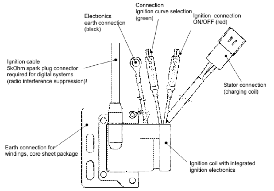
Connect all necessary ignition earth cables . Connect the stator connector to the ignition coil. Connect the ignition switch (red connector) and, for ignitions with two ignition curves, the ignition curve selector switch (green connector). In racing, cut-out switches are often used as ignition switches.
The ignition is switched off when the red connecting cable is connected to earth. When not connected, the ignition is ready for operation. In ignitions with 2 ignition curves, the first ignition curve is activated when the green connecting cable is connected to earth. When the connecting cable is not connected, the second ignition curve is active. In PVL ignitions the change between the ignition curves may take place during operation.
Fit the spark plug connector (digital ignition systems require a 5 kOhm interference-suppressed spark plug connector ! Interference-suppressed spark plugs such as DENSO Iridium Power may be used as an alternative). Plug the ignition cable into the fitted spark plug.
Ignition Timing
For vehicles originally fitted with PVL racing ignitions the Woodruff key is put in the crankshaft stub which ensures that the rotor’s position on the crankshaft is correct at all times. The stator is positioned in the crankcase according to the specifications supplied by the engine manufacturer, whilst static ignition timing as per the engine manufacturer is set by turning the stator.
For vehicles requiring retrofitting for PVL racing ignition systems you need to meet the following requirements: Max. ignition advance in degrees of crank angle as per engine manufacturer instructions or tuning level. Max. timing advance as per ignition curve diagram
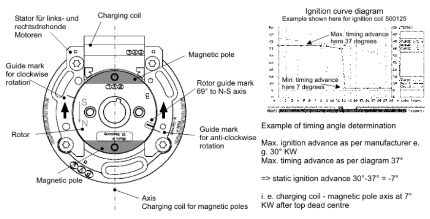
Align the stator with the rotor:
AWoodruff key is used in the crankshaft stub to lock the rotor in the correct position. Taking static
ignition advance into consideration, the stator in the crankshaft must be fixed in such a way that the
charging coil and the magnetic poles form an axis.
Static ignition advance = max. ignition advance -max. timing advance
Place the crankshaft on the static ignition advance and turn the stator until the charging coil and the
magnetic poles form an axis. The guide marks on the stator and rotor are close together.
Align the rotor with the stator
Since Woodruff keys are rarely used to fit the rotor, the rotor is aligned with the stator. Fit the stator in
the crankcase. Plan a suitable cable duct from the crankcase. Fit the stator in such a way that the
screws in the slots are roughly centred. This will allow you to fine tune the ignition timing without
having to remove the rotor again. Turn the crankshaft to the static ignition advance and fix it in this
position (piston stop). Insert the rotor and turn it on the crankshaft stub until the magnetic poles form
an axis with the charging coil . The guide marks on the stator and rotor are close together. Screw
down the rotor in this position. Loosen the crankshaft fixing device and check the setting.
Stators designed for clockwise as well as anti-clockwise engines (indicated by the second guide mark about 180° opposite), the guide mark on the rotor a nd, according to the direction of rotation, the guide mark on the stator are close together.
Installation Instructions for PVL Ignitions

Ignoring and disregarding the information contained in these Instructions could lead to damage to your new ignition and engine components! Please read through all this information and follow the relevant instructions.Your engine is an assembly of many machined components and every part has permissible production tolerances. Due to these tolerances it may be necessary to set the magnetos to suit your specific engine.
Fixing the Ignition Coil
There are two types of external coils for PVL
Ignitions. The ignition coil and the CDI module
may make up one unit, or the ignition coil and
the CDI module are two separate parts. If your
coil and the CDI module are separate, check that the
ignition coil can be fitted directly onto the chassis or
the frame with a good earth connection (absolutely
essential). If not, it may be necessary to produce a
small tab which is welded directly to the earth (part of
frame) of the vehicle. The fastening must be secure
and stable and we recommend using locknuts in order
to avoid working loose due to vibration. The CDI
Module can be fitted anywhere there is a 6 mm hole
and the wire from the module can be connected to the
coil.
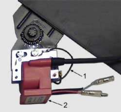
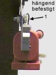
The earth cable (Item 1) from the ignition coil must be connected to the frame in a well earthed position. Without an earth cable there is a risk of overload and consequently total ignition failure Secure the earth connection (earth cable) to the coil underneath the fixing screw. If your coil and the CDI Module form one unit, the fastening will probably have to be modified in order to accommodate the PVL coil. This modification may only mean drilling new holes or perhaps cutting off the original fastening and welding on a new fastening. When fastening the coil to a fixed part of the frame (plate) it is essential that the coil holder is located in a vertical plane (vertically in a straight line from top to bottom). If the weight of a horizontally mounted coil (screwed on at the side) impinges on the coil holder from the top, then the holder will break e.g. with bumps in the road, as the weight of the ignition coil will increase greatly (acceleration due to gravity 9.81 m/s²).
Ensure that none of the cables comes into contact with the exhaust on your machine. If this happens, the insulation on the wires may melt which can cause a short circuit and possibly destroy the ignition system
In applications with particularly high vibration levels, we recommend putting some foam around the coil and binding it with insulating tape in order to avoid vibration. The black earth cable with ring connector must be earthed on the machine or engine frame. If it is not possible to fasten it on with a secure device, you can fasten the coil with any method which holds the coil securely on the frame e.g. with cable binders or in a foam sleeve with insulating tape. The black earth cable (Item 1) with ring connector must be earthed in turn on the machine or engine frame. The spark plug connector supplied with the digital system is specially designed for spark plugs with 500 Ohm resistance value. This type of connector must be used so that the system works properly.
When the coil is fitted, it can be connected to the magneto using one of two methods depending on the type of system. The analogue systems use forked cable lugs and the digital systems
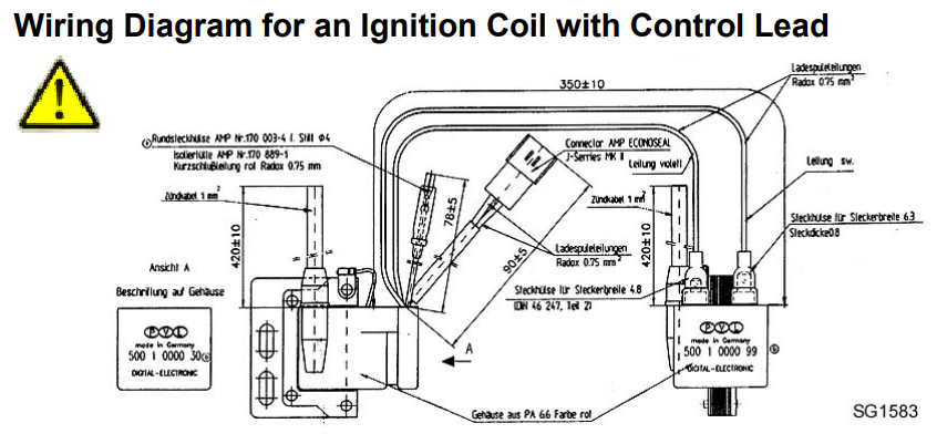
Wiring Diagram for an Ignition Coil with Control Lead
Tip
Two types of spark plug connectors are used with PVL Ignitions:
For analogue ignitions: "Standard" PVL spark plug connectors, dokutec Order No. 26602
For digital ignitions: PVL "Digital" spark plug connectors 5kOhm, dokutec Order No. 12182
,If connecting an electronic tachometer, the tachometer manufacturer mostly recommends using a 5 kOhm spark plug connector, as otherwise there may be malfunctions..
The ignition coil must be secured during installation so that vibrations during driving do not cause it to come off. The ignition coil must be earthed via the black earth cable, otherwise there is a risk of total failure. See also Ignition Coil Installation.
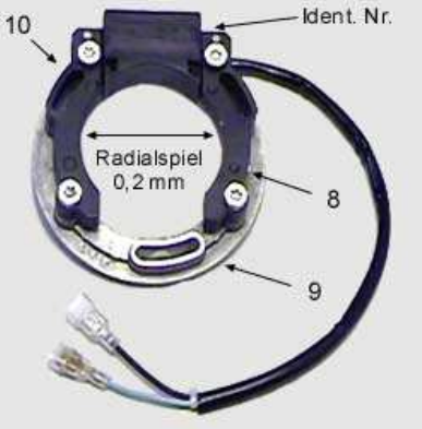
Stator & Rotor Installation
Note! Do not the remove protective strip which is wound round the rotor! It has a specific function in fitting the PVL ignition.
After removing the existing magneto from the engine, fix the PVL stator plate (depending on the manufacturer and type) together with the stator onto the engine casing. Ensure that the fixing screws do not touch any part of the engine casing ("sitting on the block", this causes dangerous voltages!). If this happens, the stator plate may be damaged or destroyed. If necessary, file or grind the ends of the screws which are too long. Leave the stator fixing screws loose in the first instance. If, in addition, an adaptor plate is fitted (between stator plate and casing e.g. if fitting in Simson S51), the adaptor plate (Item 6) must be designed so that there is an absolutely secure connection between stator plate and engine casing, otherwise damage may be caused by working loose due to vibration.
Note!
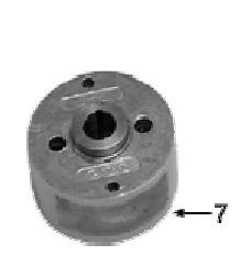
Prior to fitting the rotor (Item 7), clean the rotor bore and also the lateral journal of the crankshaft
with contact cleaner, acetone or another suitable product in order to ensure that they are free of
grease, oil or other deposits.
Put the rotor onto the crankshaft, keeping the protective strip on the rotor! A rotor of the correct
Note: When using an adaptor plate (special accessory) between engine casing and PVL stator plate (Item 9), the axial position of the rotor must be placed so that the rotor magnets are axially aligned concentrically to the stator sides (Item 8). The rotor must have sufficient radial play i.e. it must not rub against the stator. The axial position of the rotor depends on the thickness of the adaptor plate from the design point of view.
If there is not enough axial play (rotor jams) between the rotor and the sides of the stator (Item 10), loosen the four screws, which fasten the stator coil unit to the stator fixing plate, using a TORX insert or screwdriver. If the rotor fits properly, without loosening the TORX screws, continue straightaway with the ignition timing. If it is necessary to loosen the TORX screws, you must now complete the alignment procedure. Press the stator sides with your fingers (not with pliers or screwdriver) against the rotor and tighten the TORX screws. Now you can remove the protective strip from the rotor.
The ignition system must always be connected to the vehicle earth with good conductivity. The black earth cable (Item 1) on the ignition coil (Item 2) must be connected to the vehicle earth with conductivity. Never rotate the rotor of the installed ignition system without consumer (spark plug to earth)! If there is no spark plug in the connector, the ignition system has no earth and builds up excess voltage which cannot be discharged. This can cause total ignition failure!
Check manually (rotate several times) that the rotor (Item 7) can rotate without chafing. Check for too much play in the engine lateral bearings by jiggling the lateral journal on the crankshaft to and fro. If the engine lateral bearings have too much play, the rotor will start to wobble and rub against the stator.
This leads to loosening of the stator plate (Item 9) and wear on the rotor surface and magnets and finally total ignition failure. There is risk of engine damage amongst other things!
Use only the PVL extractor tool (special tool Item 11). Non-compliance with this instruction can lead to rotor damage/destruction! There are four holes drilled in the rotor. These holes are provided for fitting optional rotor weights. Only the two holes (Item 12), which are located nearest to the centre of the rotor, are intended for attaching the extractor tool! Remove the crankshaft nut using a suitable holding device. Never hold the rotor by the circumference with pliers to avoid twisting, otherwise this could cause damage to the rotor surface (magnets) and to ignition malfunctions! Attach the extractor tool in the holes provided in the rotor using the 6x50 mm screws supplied.
Screw in the screws completely so that the occurring forces cannot wreck the threads. Hold the extractor rod against twisting using an adjustable spanner. Tighten the forcing screw (Item 15), which should now touch the end of the crankshaft, using a spanner. If the rotor does not come away from the crankshaft now, hit the forcing screw hard with a light hammer in order to loosen the rotor from the crankshaft.
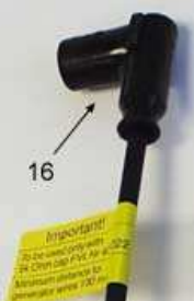
The PVL digital spark plug connector (Item 16) supplied with the digital system has a resistance value of 5 KOhm and has been tested specially for digital ignition. This type of connector must be used so that the system works properly. Using other spark plug connectors can lead to total failure. Any warranty becomes null and void in this case.
Setting the Ignition Timing
Key slots and keys (wedges) are used in series production by the manufacturers in order to enable precise setting of the ignition timing.
Note:
The rotor is not fixed to the crankshaft using the keys which are only used for accurate fixing
during assembly! If your PVL rotor does not have a keyway, this is correct from a design point of
view and no key is used. Therefore, the rotor can be positioned on the lateral journal in the 360°
crank angle range.
Tip!
With rotors without grooves, it is better to align the
stator as accurately as possible with the required
position in order to avoid repeated withdrawal of the
rotor from the lateral journal (PVL extractor tool
required) and to push the rotor onto the lateral journal
with overlapping marks only after determining the
required TDC position.
A graduated disc or a dead centre measuring device (special tool) is used to set the ignition timing in order to measure the position of the piston before top dead centre (TDC). You can set the ignition timing to the engine by aligning the marks on the rotor and the stator in conjunction with measuring the piston position before top dead centre. If the stator is located approximately in the centre of the available setting range (slots on the stator plate), tighten the stator fixing screws by touch so that it does not move by itself but can still be rotated manually. Turn the crankshaft slowly in the direction of rotation until the piston has reached the required position before TDC (e.g. 1.6 mm).
Note
Prior to rotor installation, clean the rotor bore and also the crankshaft lateral journal with contact
cleaner, acetone or another suitable product in order to ensure that they are clean and free from
grease, oil or other deposits. Install the rotor on the crankshaft so that the ignition timing mark on
the rotor corresponds to the mark on the crankshaft, see recommendations in Table A.
Many PVL stators have marks for both directions of rotation.. Ensure that the correct mark for
the direction of rotation is selected for your engine!
The following applies with rotors with grooves:
Put the rotor onto the lateral journal key to fit exactly in the groove. Place the nut by hand on the
rotor. If the piston is in the required ignition position before TDC, turn the rotor until the marks on
the rotor and stator overlap. Screw the stator down and tighten the rotor nut with the required
torque specified by the manufacturer.
The following applies with rotors without grooves:
Put the loose rotor approximately in the position where the marks on the rotor and stator overlap
and place the rotor on the lateral journal in this position. Tighten the rotor nut and screw with the
required torque.
If the mark on the stator is covered exactly by the mark on the rotor, the ignition timing is set correctly. Check the ignition timing.
Position the piston again in the required position before TDC and check that the marks on the rotor/stator still correspond. If not, simply loosen the stator fixing screws and push the stator so that the marks correspond, tighten the stator screws again correctly
If the marks cannot be aligned with correct TDC position of the piston, it is mostly due to incorrect rotor position (with rotors without grooves) and the rotor must be removed from the lateral journal
It is helpful to put marks on the casing and rotor with a permanent felt tip pen.
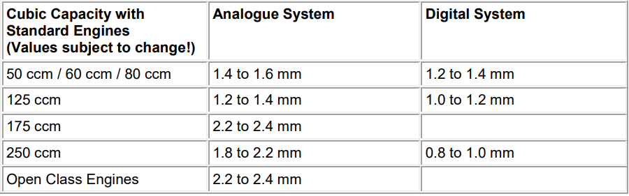
Ignition Timing Setting Values
Attention! The following setting values in Table "A" are only for reference purposes and are subject to change!
Table A
Modified engines (higher compression) require an ignition setting which is behind the above values.
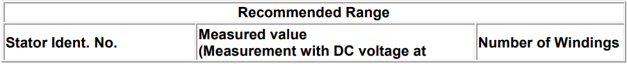
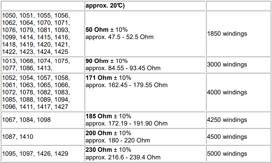
PVL Ignition Testing
Some of the PVL components can undergo a resistance test. A digital ohmmeter should be used to test PVL ignition components. Do not use an analogue measuring instrument as it is not accurate enough.
Note:
Do not test the components when they are still hot You must allow the components to cool down
to room temperature before testing!
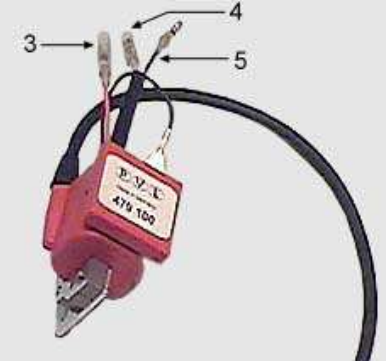
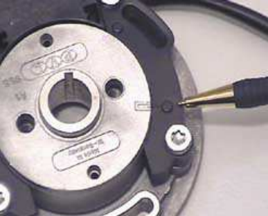
Plug a sensor into the ends of the blue and black wires respectively after releasing them from the stator coil/CDI module components. With analogue stators it does not matter which sensor is used on which wire. With digital stators you can lift a small yellow clamp with your finger nail in order to insert the sensors into the clamps on the ends of the wires. Resistance values below or way above the recommended ranges indicate that the unit being tested is faulty.
Note:
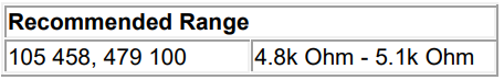
Test the ignition coil directly on the ignition cable and not via the spark plug connector. Units can
be operated with test results slightly above the recommended range. If the measured values are
in the lower range of the scale but the system is working properly, damage can be assumed. The
component should be replaced by a new one for the sake of safety, as total failure in the short
term can be assumed.
Stator No. (stamped on the stator)
Coil No. (printed on coil)
Components which cannot be resistance tested and which must be sent in for accurate testing: Digital CDI Module, 105 465 (Motoplat-compatible coil), CDI Module